35+ low level transmitter block diagram
Flex Waveguide Output flanges. 1 kW Peak Solid State Driver Amp.
How Do Vacuum Tubes And Transistors Work Quora
36 AM Transmitter Block Diagram The basic difference between the two transmitters is the power amplification.
. In low-level modulation the powers of the two input signals of the modulator stage are not amplified. The RF signal is created in the RF. The low-level AM transmitter shown in the figure b is similar to a high-level transmitter except that the powers of the.
To be radiated long Figure a shows the. Food52 vegan tres leches. How do kpop idols get their signatures.
The generating circuits for AM wave are called as amplitude modulator circuits. Our integrated circuits and reference designs enable you to build level transmitters with sensors that convert gathered measurement into an electrical representation. The modulator circuits are classified into two categories.
The AM modulation uses audio as modulating signal and. Sephora vision statement. An transmit mixer or modulator takes.
For those who want to make the PCB it is time to get the. 35 LOW LEVEL MODULATION TRANSMITTERS. Did gillon mclachlan play afl.
The block diagram can be broadly divided into two separate section viz one that - Generates an. The basic television Broadcast transmitter block diagram is shown in figure a. Rt 1694 prc 150 hf receiver transmitter.
In this block diagram of communication system the upper section is called the transmitting section. Millstone Hill Radar Transmitter Room. The radio transmitter works block diagram of a simple AM amplitude modulated signal transmitter is shown on Pic22.
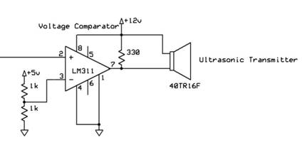
Figure b shows the block diagram of a low-level AM transmitter. Low Level AM Transmitter Block Diagram There are two signal paths in the transmitter audio frequency AF and radio frequency RF. Simple Transmitter Block Diagram DAC PLL VCO Transmit Chain LNA Diplexer PA Digital bits get converted to analog waveforms through DAC and lter.
Most durable fabric for clothing.
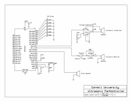
Ece 476 Final Project

Nor Flash Solutions Rutronik
Aerospace Free Full Text Heavy Ion Induced Single Event Effects Characterization On An Rf Agile Transceiver For Flexible Multi Band Radio Systems In Newspace Avionics Html
Ece 476 Final Project
Why Do We Use Lc Circuits For Generating High Frequency And Rc Circuits For Generating Low Frequency Signals Quora
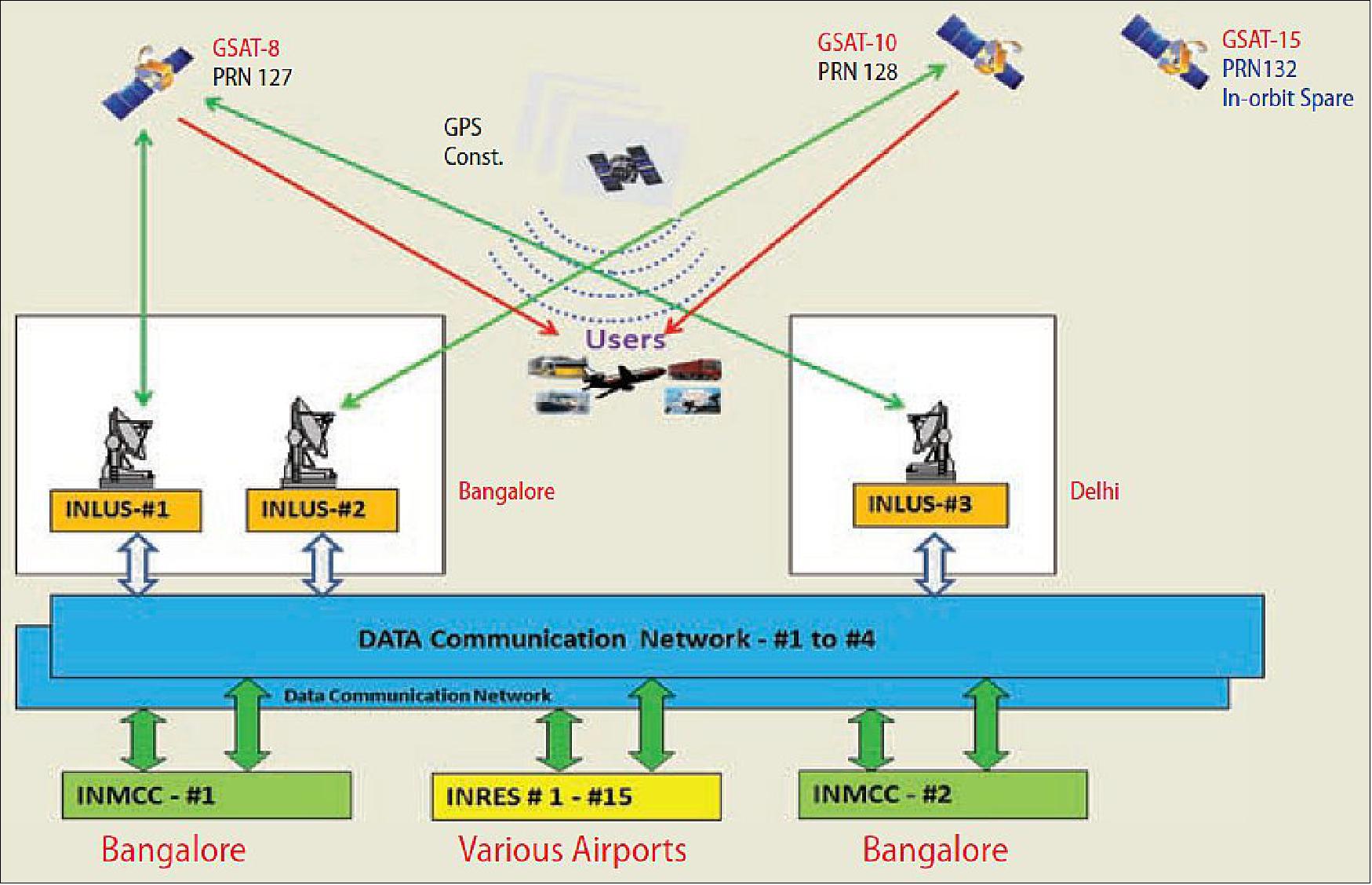
Sbas

Closed Tank Remote Seal Capillary Type Dp Transmitter Transmitter Steam Boiler Remote
What Is The Purpose Of Using A Low Noise Amplifier In Rf Receivers Why Can T A Power Amplifier Be Used In An Rf Receiver Quora
Is It Necessary To Use Diodes In Making An Fm Radio Quora

Fm Transmitter Fm Transmitters Electronics Circuit Electronic Engineering

Calibration And Initialization Of Rosemount 3051cd Capillary Type Level Transmitter Transmitter Rosemount Levels
2

Closed Tank Level Measurement Using Dp Transmitters Instrumentation Tools Transmitter Measurements Tank
2
Why Do We Use Lc Circuits For Generating High Frequency And Rc Circuits For Generating Low Frequency Signals Quora
Aerospace Free Full Text Heavy Ion Induced Single Event Effects Characterization On An Rf Agile Transceiver For Flexible Multi Band Radio Systems In Newspace Avionics Html
2